
Adding Networking Services to a VM and Integration with Junos
This post shows a guideline for basic installation of an Ubuntu VM in order to provide basic networking services like NTP, Syslog, RADIUS, FTP, and Cacti Monitoring server for Juniper SRX Router/Firewall. It’s going to be a long post so you’d better fasten your seat belt.
Prerequisites
- vMX/vSRX
- Any Linux based image
- VMware/Virtual Box/ESXi
Here we’ll be using vSRX image and Ubuntu Desktop emulated on VMware workstation, below you can find how to setup vSRX on VMware if you needed a reference.
Installation
First we’ll start by preparing the VM so as to be able to provide these services.
You’ll need to add 2 NIC for the Ubuntu VM so that you can get Internet access from one NIC and to connect to the SRX via the other NIC. Here we have adapter1 connected as NAT interface, and adapter 2 in connected to the same VMNET/LAN segment of the SRX.

OSPF Type-4 LSA
Have you ever questioned your self, why on earth do we need OSPF type-4 LSA ? well, you are not the only one. Welcome to this blog post where we’ll try to discover the actual worth of that LSA.
First let’s examine the below graph, where we have a basic implementation of multi-area OSPF. R1 RID is 1.1.1.1, R2 RID is 2.2.2.2, R3 RID is 3.3.3.3, and we have network 200.200.200.0.24 redistributed to OSPF area 1 by area 1 ASBR; R1.

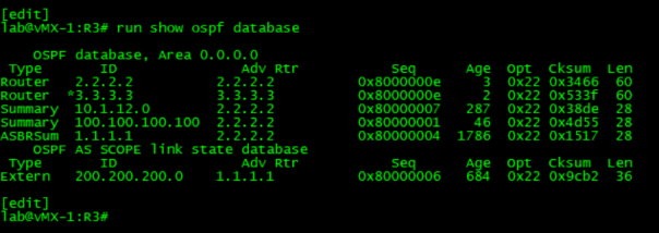
We’ll start by examining the contents of the Link State Data Base (LSDB) of R3 for the external prefix 200.200.200/24;


When we look extensively at the type-5 LSA of prefix 200.200.200/24 in the LSDB of R3, we can see that it has an advertising router of 1.1.1.1 and a FW addr: 0.0.0.0.
The 1.1.1.1 is the RID of the advertising router, while the forwarding address is a way to that can be used to route traffic in another direction than to the router that originated the LSA. Having a value of 0.0.0.0 as the FW addr essentially tells other routers to forward packets for that destination to the router that advertised the LSA.
However when looking closely, we can see that R3 LSDB also has a type-3 LSA for 1.1.1.1/32, so the question that popped out of my mind was “If there is a valid reachable type-3 for 1.1.1.1/32, then why do I need Type-4 LSA?”.
After taking a while looking into the issue I realized what went wrong. Well, I made a mistake, the 1.1.1.1/32 summary LSA was not the same 1.1.1.1 that advertised the external LSA. So what is the difference ?
Here’s were everything starts to get clear, we all network engineers have the convention that OSPF RID is driven from the highest loopback interface IP address present on the router and in case of the absence of loopback interfaces, the highest physical interface IP address well be chosen as the OSPF RID of the router, here is the catch, OSPF RID is a node-identifier. It usually uses an IPv4 address format, but it is an ID and does not need to match any interface present on the router.
Ok then, let’s try something, we’ll change the IP address of the lo0.0 of R1 to 100.100.100.100/32 and see what happens.
If we examined the external LSA of prefix 200.200.200.0/24 we notice that it still has the 1.1.1.1 as an advertising router, but wait, where is the LSA type-3 that was advertising 1.1.1.1/32, it’s no longer there and was replaced with 100.100.100.100/32 that is the new lo0.0 address of R1 that was already included under protocol ospf hierarchy of the configuration stanza. So the only way to reach the RID of R1 1.1.1.1 and consequently the external prefix 200.200.200/24 is by following the information contained in the ASBRSum LSA.
As you notice, our small lab was fruitful and we can conclude the following:
- Routers in other areas see a Type-5 with a meaningless RID. They might have a type-3 prefix that looks like the ASBRs RID, but this doesn’t help it find the ASBR.
- The type-4 LSA generated by the ABR is needed as a glue record, so that routers can ‘anchor’ the unknown ASBR RID against as reachable via a well-known node, the local ABR.
I hope this was informative and thank you for viewing.
Trouble Shooting OSPF Adjacency Problems (3)
In today’s post we are going to resume our discussion about the reason that could lead to OSPF adjacency problems, and we’ll look into the below reasons:
- Mismatched hello and dead interval values.
- Mismatched MTU settings.
We’ll work on the same topology as below.

Trouble Shooting OSPF Adjacency Problems (2)
In the last post we’ve discussed some of the reasons that could lead to OSPF adjacency problems, in today’s post we are going to look at the below reasons and we shall continue the rest of the reasons in a subsequent post.
- Mismatched interface types.
- OSPF priority is set to 0 on both sides.
- Mismatched area IDs or mismatched area types.
We’ll continue to work on the same topology as below.
Trouble Shooting OSPF Adjacency Problems (1)
In this topic we are going to discuss some of the reasons that affect the OSPF adjacency between two peers and how to trouble shoot these issues in Junos.
First we will list the possible reasons for OSPF adjacency issues and we’ll discuss it in detail in subsequent paragraphs.
Possible Causes of OSPF Adjacency Issues:
- Duplicate RIDs.
- Mismatched subnet masks, or incorrect IP addressing.
- Authentication mismatches.
- Mismatched interface types.
- OSPF priority is set to 0 on both sides.
- Mismatched area IDs or mismatched area types.
- Mismatched hello and dead interval values.
- Mismatched MTU settings.
Juniper Aggregated Ethernet Interfaces
Overview
In this blog, we’ll be discussing one of the most High Availability protocols that’s broadly used in today’s networks that is Link Aggregation Control Protocol (LACP) and Link Aggregation Groups (ALG)
LACP is a method of bundling several physical interfaces to form one logical interface, which is advantageous in providing more bandwidth and increasing redundancy, On Cisco devices this is referred to as Ether-Channel.
It’s worth noting that the load-balancing hash algorithm for IP traffic uses criteria at Layer 2, Layer 3, and Layer 4. No configuration is necessary to enable load balancing. The load-balancing hash algorithm for non-IP traffic uses source and destination MAC addresses.
LACP exchanges are made between actors and partners. An actor is the local interface in an LACP exchange. A partner is the remote interface in an LACP exchange. LACP is defined in IEEE 802.3ad, Aggregation of Multiple Link Segments and was designed to achieve the following:
- Automatic addition and deletion of individual links to the aggregate bundle without user intervention
- Link monitoring to check whether both ends of the bundle are connected to the correct group
Note that the Junos OS implementation of LACP provides link monitoring but not automatic addition and deletion of links.
The LACP mode can be active or passive. By default, when LACP is configured its mode defaults to the passive mode on aggregated Ethernet interfaces. To initiate transmission of LACP packets and response to LACP packets, you must enable LACP active mode.
Note that LACP exchanges protocol data units (PDUs) across all member links to ensure each physical interfaces is configured and functioning properly. Read the rest of this entry
L2 And L3 VPN over Ethernet Ring
In this post we are going to discuss how can we setup L2VPN and L3VPN over an Ethernet ring network, this is very challenging actually, knowing the fact that we need to achieve redundancy for both our edge network and to our customer.
As illustrated below, we have our MX104 PE router connected to the ring network that’s connected to MSAN cabins (Access Layer) through 2 Gigabit interfaces in order to achieve redundancy over the network.

The 1st challenge to take is how to setup L3VPN.
In our situaion we can’t use a logical unit of one of the main Gigs as this will not achieve the needed redundancy for the customer as there’s one Gig that will be up and the other will be down in order to prevent loops. So the right solution would be to use Integrated Routing & Bridging interfaces (IRB) and assign it to the same bridge domain as the logical units of the main Gigs.
| root@R02J> show interfaces descriptions | match Cust-A ge-0/0/1.700 up up VPN: Cust-A –> Main Gig the customer is working on right now ge-0/1/1.700 up down VPN: Cust-A –> Backup Gig for the same customer irb.700 up up VPN: Cust-A –>Layer 3 IRB interface for this customer (like an SVI interface on a Cisco Switches) |
Understating Cisco IOS v15 Licensing
IOS 15 is a single software package for the hardware platform that your are using. Now that flash is cheap and large, there doesn’t need to be a different IOS image for the different versions with the advanced features. So you get one software image that has all the features for that platform.
Prior to IOS 15 , we used to have 8 IOS images, all routers came with IPBase image and according to your needs you can choose what IOS image to install on your router as each image had different features than others as illustrated below.

Use of EEM Scripting for Special Hot Backup Solutions
In this blog I would like to share some information about some special Hot backup solutions that we are forced to deal with due to customer requirements.

In the above figure, we have a customer that’s connected to the ISP through 2 Links, the Main link is a Pre-WiMax connection that’s carrying customer’s Internet and VPN traffic and configuration on the PE router is as below.
PE#show run int Fast1/0.100
Building configuration…
Current configuration : 184 bytes
!
interface FastEthernet1/0.100
description “Main Internet Link Pre-WiMax”
encapsulation dot1Q 100
ip address 190.200.200.1 255.255.255.0 secondary
ip address 172.16.1.1 255.255.255.252
end
PE#show run int Fast1/0.200
Building configuration…
Current configuration : 156 bytes
!
interface FastEthernet1/0.200
description “Main VPN Link Pre-WiMax”
encapsulation dot1Q 200
ip vrf forwarding VPN-A
ip address 172.17.1.1 255.255.255.252
end Read the rest of this entry
OSPF Domain-ID || Domain-Tag
OSPF Domain ID
When OSPF is used as the routing protocol on a provider edge to customer edge (PE-CE) link in a multiprotocol label switching (MPLS) VPN. PE routers mark OSPF routes with the domain attribute derived from the OSPF process number to indicate whether the route originated within the same OSPF domain or from outside it.
Importance of Domain-ID
In MPLS-VPN network ISP cloud is treated as a super backbone area, and PEs are considered as ABRs or ASBRs depending on the domain-id value, then routes redistributed to CEs would be OSPF inter- area routes or would be OSPF external routes.
Why would we care to have OIA or E or O routes in our OSPF database?
The answer is simply that OSPF prefers intra-area routes then inter-area routes and finally external routes to be installed in routing table. And we don’t want to come in to the case that routes are leaked from a back door in then being redistributed to the ISP cloud creating a loop in the network and disrupting traffic.
So if we had a different processes on our PEs then so we have to explicitly configure the domain-id value under the OSPF process.
OSPF loop prevention in PE-CE routing
- DN bit
o When a type 3 LSA is sent from a PE router to a CE router, the DN bit [OSPF-DN] in the LSA Options field MUST be set. This is used to ensure that if any CE router sends this type 3 LSA to a PE router, the PE router will not redistribute it further.
- Domain-Tag
o PE routers originate Type 5 LSAs reporting the extra-domain routes as AS-external routes. Each such Type 5 LSA MUST contain an OSPF route tag. This tag identifies the route as having come from a PE router. The VPN Route Tag MUST be used to ensure that a Type 5 LSA originated by a PE router is not redistributed through the OSPF area to another PE router.
